Welcome: SANYO DENKI San Ace cooling fan product chain in China region
Language:
 ∷

∷
 ∷

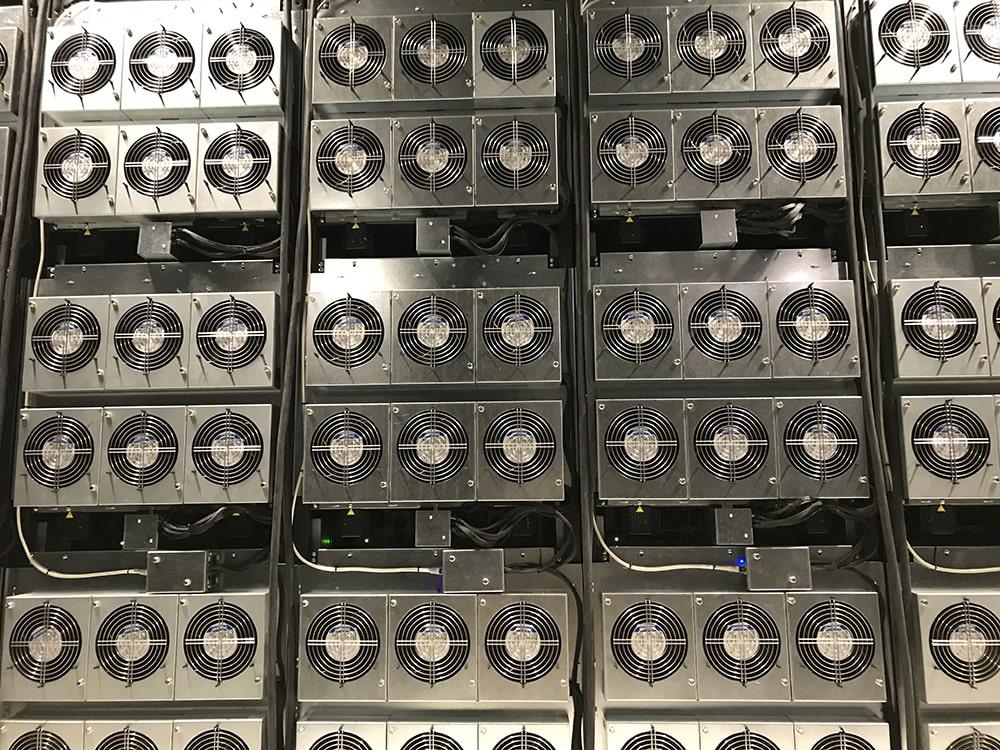
As servers, telecommunications equipment, industrial power supplies, and new energy systems continue to increase in power density, internal cooling space is becoming more limited while heat generation continues to rise.
In these high-density cooling applications, conventional axial fans may struggle to meet both airflow and static pressure requirements. To improve airflow performance, some engineers consider installing two conventional fans in series.
But can two ordinary fans installed in series deliver the same performance as a professional Counter Rotating Fan?
Not necessarily.
Although both configurations use two stages of airflow movement, they differ significantly in impeller rotation direction, aerodynamic design, motor configuration, drive circuitry, and overall performance matching.
To address the growing demand for high airflow and high static pressure, SANYO DENKI developed the San Ace Counter Rotating Fan series. By redesigning the impellers, frame, motor, and drive circuit, the series is optimized for airflow, static pressure, and efficiency, providing an advanced cooling solution for high-density equipment.
In conventional equipment, cooling fans generally need to move air through relatively open ventilation paths to provide sufficient cooling.
However, modern high-density equipment presents several new challenges:
Limited installation space: Servers, communication equipment, and industrial control systems contain increasingly compact internal components, leaving less room for cooling fans.
Higher heat generation: High-performance processors, power modules, and electronic components generate more heat.
Increased airflow resistance: Dense heatsinks, filters, ventilation ducts, and complex internal structures restrict airflow.
Higher cooling requirements: Equipment requires not only sufficient airflow but also adequate static pressure to maintain effective airflow against system resistance.
Therefore, fan selection should not be based on maximum airflow alone. Static pressure and the actual operating point of the fan are equally important.
This is one of the reasons Counter Rotating Fans have attracted attention in high-density cooling applications.
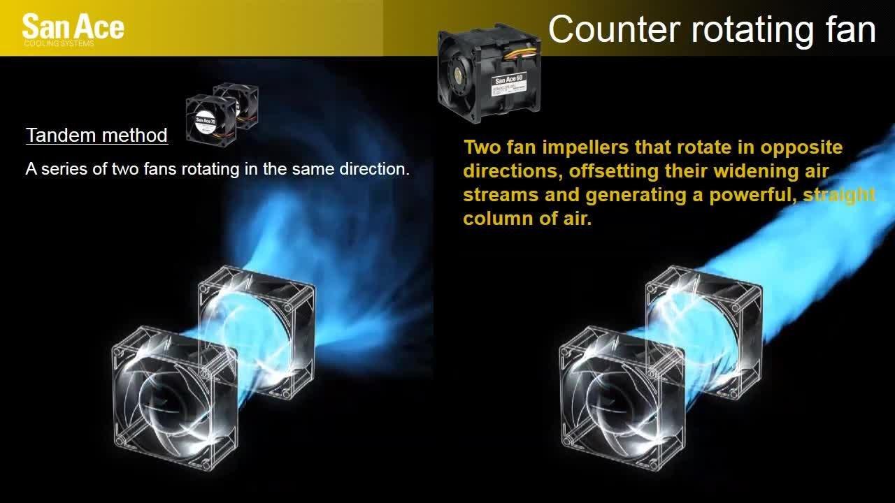
First, it is important to distinguish between two configurations.
Conventional Dual Fans in Series: Two standard axial fans are installed one behind the other along the same airflow path. Their impellers generally rotate in the same direction.
Counter Rotating Fan: Two specially designed impellers are arranged in front and rear stages and rotate in opposite directions. The impellers, frame, motor, and drive circuit are designed to work together as an integrated system.
Although both configurations may use a thick, two-stage structure, they are not the same fan design.
In a conventional series configuration, two axial fans are installed sequentially along the same airflow path.
The first fan pushes air forward, while the second fan continues to add energy to the airflow.
Under properly matched operating conditions, connecting fans in series can increase the pressure capability of the system. This arrangement may be useful in applications where additional pressure is required to overcome airflow resistance.
However, conventional fans are often initially designed for individual operation. When two fans are combined, the second fan receives airflow that has already been affected by the first fan.
The velocity distribution and rotational characteristics of the incoming airflow may therefore change.
If impeller design, installation spacing, and operating conditions are not properly matched, airflow interference, reduced efficiency, or increased noise may occur.
A Counter Rotating Fan typically uses two impellers arranged sequentially along the same axis.
The first impeller drives the airflow and introduces a rotational component. The second impeller rotates in the opposite direction, performs additional work on the airflow, and helps manage the rotational component generated by the first stage.
Through coordinated aerodynamic design, this configuration can improve airflow, static pressure, and overall efficiency.
| Comparison | Conventional Dual Fans in Series | Counter Rotating Fan |
|---|---|---|
| Configuration | Two standard fans installed sequentially | Two specially designed impeller stages |
| Impeller rotation | Generally same direction | Opposite directions |
| Airflow operation | Two stages of same-direction airflow acceleration | Two stages of coordinated counter-rotation |
| Impeller design | Often designed for individual operation | Designed to work together as a two-stage system |
| Motor and drive | Independent or coordinated operation | Dedicated drive design for counter-rotation |
| Performance objective | Increase system pressure capability | Optimize airflow, static pressure, and efficiency |
| Typical applications | General high-resistance airflow systems | High-density, high-airflow, high-static-pressure cooling |
It is important to note that conventional fans in series are not necessarily inferior, and Counter Rotating Fans are not automatically better under every operating condition.
Actual performance depends on fan curves, system resistance, installation conditions, and testing results.
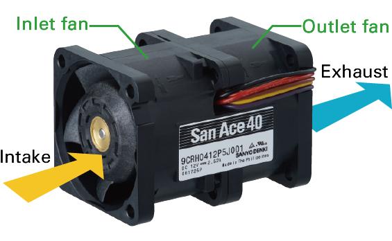
A professional Counter Rotating Fan is more than two ordinary fans combined into one assembly.
To meet the demand for higher airflow and static pressure, SANYO DENKI redesigned the impellers, frame, motor, and drive circuit to improve airflow performance, static pressure, and efficiency.
The main design considerations include:
1. Aerodynamic Impeller Design
The two impellers must be properly matched in terms of blade geometry, rotation direction, and operating conditions.
The airflow characteristics produced by the first impeller directly affect the operating performance of the second impeller.
2. Frame and Airflow Passage Design
The frame provides mechanical support and also influences how air enters, passes through, and exits the fan.
An optimized airflow passage helps reduce unnecessary airflow losses.
3. Motor and Drive Circuit Design
The counter-rotating structure requires the front and rear impellers to rotate in opposite directions while maintaining appropriate operating conditions.
The motor and drive circuit must therefore be designed to support the overall aerodynamic configuration.
4. PWM Speed Control
PWM-compatible models allow users to adjust fan speed through an external control signal.
By setting the minimum speed required for cooling, equipment designers can reduce unnecessary power consumption and operating noise.
For example:
When equipment operates under a light load, fan speed can be reduced.
When internal temperature rises, fan speed can be increased.
Under high-load conditions, the fan can operate at a higher speed according to cooling requirements.
This is particularly useful for servers, communication equipment, and industrial systems that operate continuously.
The SANYO DENKI San Ace Counter Rotating Fan series offers multiple performance options to meet different voltage, speed, airflow, and static pressure requirements.
According to the supplied product specifications, the series reaches a maximum rotational speed of 18,500 min⁻¹, maximum airflow of 5.7 m³/min (approximately 201 CFM), and maximum static pressure of 2,700 Pa (10.8 inH₂O).
| Model | Voltage | Power | Speed (min⁻¹) | Max. Airflow (m³/min) | Max. Airflow (CFM) | Max. Static Pressure (Pa) | Noise (dBA) |
|---|---|---|---|---|---|---|---|
| 9CRH0812P8G001 | 12V | 120W | 15,400 | 5.7 | 201 | 1,950 | 82 |
| 9CRH0848P8G001 | 48V | 120W | 15,400 | 5.7 | 201 | 1,950 | 82 |
| 9CRB0812P8G001 | 12V | 110.4W | 14,600 | 5.5 | 194 | 1,150 | 80 |
| 9CRE0812P8G001 | 12V | 63.6W | 12,000 | 4.5 | 158.9 | 1,150 | 76 |
| 9CRA0812P8G001 | 12V | 63.6W | 12,000 | 4.5 | 158.9 | 1,150 | 76 |
| 9CRA0812P8H001 | 12V | 39.6W | 10,000 | 3.75 | 133.9 | 798 | 72 |
| 9CRA0824P8G001 | 24V | 63.6W | 12,000 | 4.5 | 158.9 | 1,150 | 76 |
| 9CRA0848P8G001 | 48V | 63.4W | 12,000 | 4.5 | 158.9 | 1,150 | 76 |
| 9CRHA0812P8J001 | 12V | 144W | 18,500 | 5.65 | 199 | 2,700 | 85 |
| 9CRHA0848P8J001 | 48V | 135W | 18,500 | 5.65 | 199 | 2,700 | 85 |
Note: The specifications above are organized from the supplied product data. Maximum airflow and maximum static pressure generally correspond to different operating points on the fan performance curve. They should not be interpreted as being achieved simultaneously. Please refer to the official specifications and test conditions for each model.
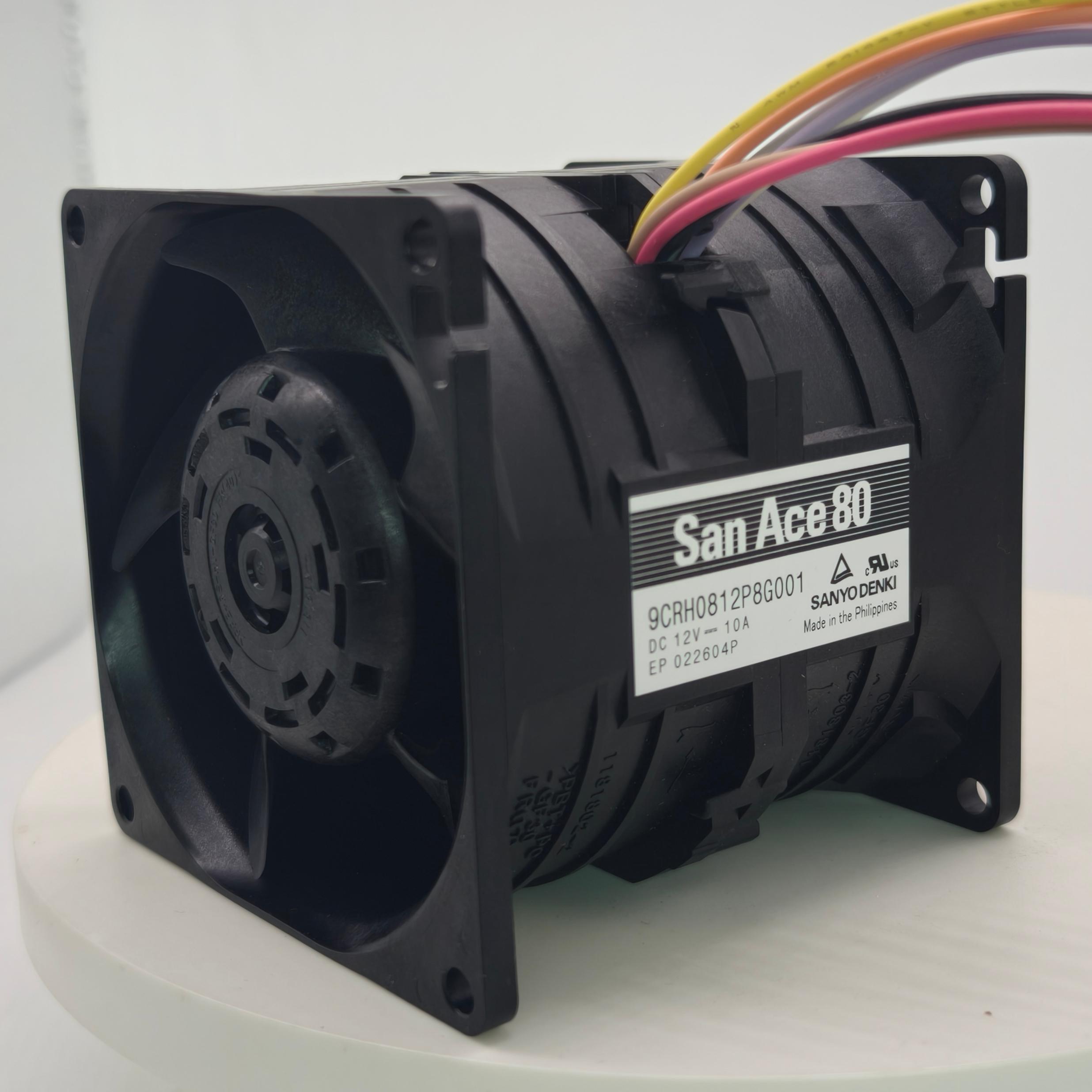
The San Ace 80×80×80mm Counter Rotating Fan series offers different performance levels for different cooling requirements.
High Static Pressure: 9CRHA Series
Models 9CRHA0812P8J001 and 9CRHA0848P8J001 operate at up to 18,500 min⁻¹, with maximum static pressure of 2,700 Pa and maximum airflow of 5.65 m³/min.
These models are suitable for evaluation in high-resistance cooling systems, such as dense heatsinks, complex airflow passages, and high-heat-load equipment.
Their specified noise level is 85 dBA, so acoustic requirements should also be considered during selection.
High Airflow: 9CRH Series
Models 9CRH0812P8G001 and 9CRH0848P8G001 operate at 15,400 min⁻¹, delivering maximum airflow of 5.7 m³/min, approximately 201 CFM, and maximum static pressure of 1,950 Pa.
They are suitable for applications requiring high airflow together with substantial static pressure capability.
Balanced Airflow and Static Pressure: 9CRB Series
Model 9CRB0812P8G001 operates at 14,600 min⁻¹, with maximum airflow of 5.5 m³/min and maximum static pressure of 1,150 Pa.
It can be considered for applications requiring high airflow and a certain level of static pressure capability.
Alternative Options for Power and Noise Requirements: 9CRA and 9CRE Series
Model 9CRA0812P8H001 operates at 10,000 min⁻¹, with maximum airflow of 3.75 m³/min, maximum static pressure of 798 Pa, and noise level of 72 dBA.
Selected G-grade models in the 9CRA and 9CRE series offer maximum airflow of 4.5 m³/min, maximum static pressure of 1,150 Pa, and noise level of 76 dBA.
Compared with the higher-speed J-grade models, these options provide different performance configurations for applications with varying cooling requirements.
The final model should be selected according to the actual system operating point, acoustic limits, and power supply conditions.
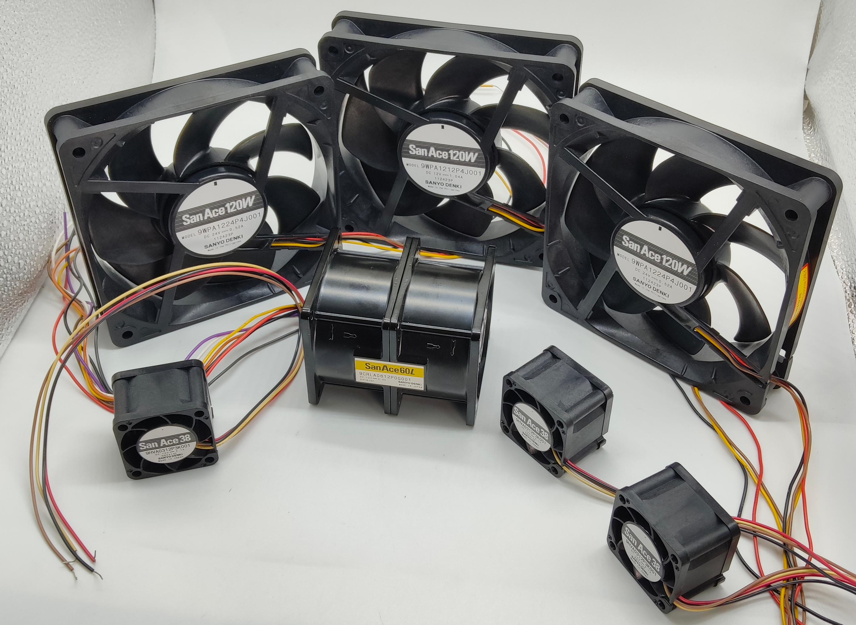
In addition to high airflow and static pressure, the San Ace Counter Rotating Fan series features PWM control and Pulse Sensor speed monitoring.
PWM Speed Control
PWM (Pulse Width Modulation) is a widely used method of fan speed control.
The equipment control system can adjust fan speed according to temperature sensors, load conditions, or predefined cooling strategies.
For example:
Reduce fan speed when equipment load is low.
Increase fan speed when internal temperature rises.
Adjust fan speed according to cooling demand under high-load conditions.
By setting the minimum necessary fan speed, users can reduce unnecessary power consumption and operating noise.
Pulse Sensor
The listed models are equipped with Pulse Sensors that provide rotational speed signals to the equipment control system.
These signals can be used to monitor fan operation and detect abnormal conditions, such as fan stoppage or rotational speed deviations.
For equipment requiring long-term continuous operation, speed monitoring helps improve the overall thermal management system.
The San Ace Counter Rotating Fan series is designed to address high-airflow and high-static-pressure requirements in high-density equipment.
Its 80×80×80mm configuration can be considered for the following applications:
1. Servers and Data Center Equipment
Processors, accelerator cards, and power modules generate substantial heat within compact server enclosures. Dense heatsinks and restricted airflow passages can increase system resistance.
Counter Rotating Fans can be considered as a cooling option for high-density server systems.
2. Telecommunications Equipment and Network Racks
Communication equipment contains multiple compact modules and often operates continuously. High-static-pressure fans can help move air through dense components and internal airflow passages.
3. Industrial Power Supplies and UPS Systems
High-power power supplies and UPS equipment generate heat during operation. Internal heatsinks and electronic components may create considerable airflow resistance.
Fan selection should be based on actual thermal requirements and airflow path design.
4. New Energy and Power Electronics Equipment
Energy storage converters, inverters, and other power electronic systems require reliable thermal management.
Counter Rotating Fans can be evaluated according to equipment heat load, installation space, and operating environment.
5. High-Density Cooling Modules
For cooling modules with limited installation space but demanding airflow and static pressure requirements, Counter Rotating Fans provide another airflow design option.
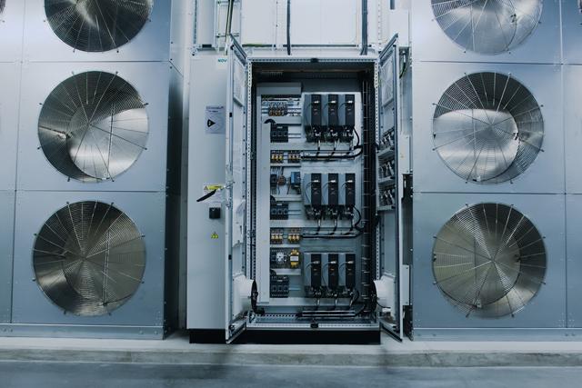
Whether choosing conventional fans in series or a Counter Rotating Fan, the final selection must be based on actual equipment operating conditions.
Engineers should consider the following factors:
1. Determine the Equipment Heat Load
Calculate the heat generated inside the equipment and identify the required heat removal capacity and allowable temperature rise.
2. Evaluate System Airflow Resistance
Heatsinks, filters, air inlets and outlets, duct bends, and internal components all contribute to airflow resistance.
3. Review the Fan P-Q Curve
The P-Q curve illustrates the relationship between airflow and static pressure.
The fan performance curve should be evaluated together with the system resistance curve to determine the actual operating point.
4. Verify Voltage and Power Requirements
The 80×80×80mm Counter Rotating Fan series includes high-performance models with substantial power requirements.
Check power supply capacity, startup conditions, and available electrical margin before installation.
5. Consider Noise and Speed Control
High-speed, high-static-pressure fans may produce considerable noise. For equipment requiring dynamic cooling control, PWM-compatible models can be considered.
6. Conduct System-Level Testing
Temperature rise, airflow, noise, and continuous operation should be verified under actual installation conditions to confirm compatibility between the fan and the equipment.
Two conventional axial fans installed in series can improve system pressure capability through two stages of airflow work. However, this arrangement is not equivalent to a professionally designed Counter Rotating Fan.
A Counter Rotating Fan uses two impellers rotating in opposite directions, supported by coordinated design of the impellers, frame, motor, and drive circuit. This approach is intended to optimize airflow, static pressure, and efficiency.
The SANYO DENKI San Ace 80×80×80mm Counter Rotating Fan series offers multiple performance options, with maximum rotational speed of 18,500 min⁻¹, maximum airflow of 5.7 m³/min, and maximum static pressure of 2,700 Pa. Selected models also support PWM speed control and Pulse Sensor monitoring.
For servers, telecommunications equipment, industrial power supplies, new energy systems, and high-density cooling modules, fan selection should not rely on a single maximum specification.
Instead, engineers should consider actual system resistance, heat load, acoustic requirements, installation space, and control strategy.
Looking for an 80×80×80mm high-static-pressure axial cooling fan? Contact the San Ace cooling fan team to learn more about SANYO DENKI Counter Rotating Fan models, performance specifications, and application selection support.
Contact: Mr. Wang
Phone: 18148574796
Tel: 0755-23706799
Email: wmc@jentech.cn
Add: No. 28, Tongyuwu Industrial Zone, Kuikeng Community, Guanlan Street, Longhua District, Shenzhen City. 6th floor, Building 1, Hualangjia Industrial Park
 Click to inquire