SANYO DENKI San Ace 9BMB24H201 24V DC Blower for Compact Equipment Cooling
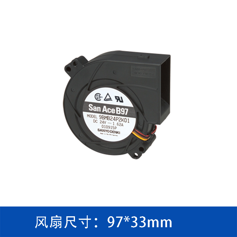
The SANYO DENKI San Ace 9BMB24H201 is a 24V DC blower designed for applications where effective airflow needs to be delivered through a relatively compact cooling structure. As part of the San Ace blower fan series, this model combines a 97 × 33 mm form factor with a maximum airflow of 39.2 CFM and a maximum static pressure of 490 Pa.
For equipment designers, the value of a blower is not simply its airflow rating. The ability to redirect airflow and maintain airflow performance against system resistance can be equally important when the internal structure of the equipment contains ducts, heat sinks, filters or other airflow restrictions.
1. Compact 97 × 33 mm Blower Design
The 9BMB24H201 has a nominal size of 97 mm × 33 mm, providing a compact alternative to conventional axial cooling fans when the equipment requires a different airflow direction.
Unlike an axial fan, a blower can discharge air approximately 90 degrees from the intake direction. This configuration can make it easier for engineers to integrate the cooling airflow into compact equipment without relying on an additional external duct.
This characteristic is particularly useful where:
-
Internal installation space is limited
-
Heat sources are concentrated in a specific area
-
The airflow needs to be redirected
-
A compact cooling path is required
-
The system has relatively high airflow resistance
For equipment with a constrained internal layout, the mechanical airflow path can be just as important as the fan's nominal airflow specification.
2. 24V DC Operation for Industrial Equipment
The 9BMB24H201 operates at a rated voltage of 24V DC.
A 24V DC power architecture is commonly used in industrial and electronic equipment because it can be integrated with existing DC power systems and control circuits.
For this model, the rated electrical specifications are:
|
Specification
|
9BMB24H201
|
|
Product type
|
DC Blower
|
|
Fan size
|
97 × 33 mm
|
|
Rated voltage
|
24 V
|
|
Rated current
|
0.55 A
|
|
Rated power
|
13.2 W
|
|
Rated speed
|
4,850 min⁻¹
|
|
Maximum airflow
|
1.11 m³/min / 39.2 CFM
|
|
Maximum static pressure
|
490 Pa / 1.968 inchH₂O
|
|
Noise level
|
57 dBA
|
|
Sensor
|
Pulse sensor
|
|
PWM control
|
Yes
|
|
Expected life
|
40,000 h at 60°C / 70,000 h at 40°C
|
These specifications make the model suitable for applications where a controlled 24V cooling solution is required.
3. 490 Pa Static Pressure for Airflow-Resistant Systems
One of the important specifications of the 9BMB24H201 is its maximum static pressure of 490 Pa.
When selecting a cooling fan, maximum airflow alone does not determine whether the fan will perform effectively inside the actual equipment.
In a real cooling system, airflow resistance can be generated by:
-
Heat sinks
-
Air filters
-
Narrow air passages
-
Protective grilles
-
Internal ducts
-
High-density components
-
Cable and structural obstructions
As system impedance increases, the actual operating airflow decreases.
This is where the pressure capability of a blower becomes important. The 9BMB24H201 can generate up to 490 Pa of static pressure, providing pressure capability for cooling systems where airflow must pass through a defined internal path.
Therefore, engineers should evaluate the fan based on its P-Q performance curve and actual system operating point, rather than selecting a fan solely according to its maximum CFM value.
4. 39.2 CFM Maximum Airflow
The maximum airflow of the 9BMB24H201 is 1.11 m³/min, equivalent to 39.2 CFM.
This airflow capacity provides a useful cooling solution for compact electronic equipment where heat must be moved away from internal components.
However, maximum airflow is normally measured under a low-resistance condition. The airflow available after installation depends on the equipment's actual system impedance.
For this reason, the appropriate selection process should consider both:
Required airflow + required static pressure
rather than airflow alone.
For example, if a compact enclosure contains a dense heat sink and a narrow outlet, a fan with a higher pressure capability may maintain useful airflow more effectively than a fan with a higher free-air CFM rating but lower static pressure.
5. PWM Control for Cooling Management
The 9BMB24H201 supports PWM control, allowing the equipment controller to adjust fan operating conditions according to the thermal requirements of the system.
PWM control can be useful when the equipment does not continuously operate at its maximum thermal load.
For example, the cooling system can be designed to operate at different fan speeds according to:
-
Internal temperature
-
CPU or processor load
-
Power module temperature
-
Equipment operating mode
-
Ambient temperature
-
System power consumption
Instead of operating the blower continuously at maximum speed, the control system can adjust the fan according to the thermal condition of the equipment.
This can help balance cooling performance, acoustic performance and power consumption.
6. Pulse Sensor for Fan Monitoring
The 9BMB24H201 is equipped with a pulse sensor.
Fan feedback signals can be integrated into the equipment controller to monitor the operating condition of the cooling system.
This is useful in equipment where cooling fan operation is related to overall system reliability.
If the controller detects an abnormal fan speed or loss of expected pulses, it can potentially trigger an alarm, maintenance notification or protective control strategy.
For continuously operating equipment, fan monitoring can therefore become part of the overall thermal management architecture rather than being treated as an independent component function.
7. 57 dBA Noise Level
The specified noise level of the 9BMB24H201 is 57 dBA.
Blowers with higher pressure capability can generate noticeable aerodynamic noise, especially when operating at high speed or when installed in restrictive airflow paths.
Therefore, the actual acoustic performance of a blower should be evaluated together with the equipment structure.
The following factors can influence the final noise level:
-
Fan operating speed
-
Airflow resistance
-
Outlet geometry
-
Duct configuration
-
Mounting structure
-
Vibration transmission
-
Fan control strategy
For applications with strict acoustic requirements, engineers should evaluate the complete fan-and-system configuration rather than relying only on the catalog noise value.
8. Expected Service Life
The stated expected life of the 9BMB24H201 is:
-
40,000 hours at 60°C
-
70,000 hours at 40°C
The operating environment has a direct influence on cooling fan service life. Continuous operation at elevated temperature can place greater thermal stress on the motor and electronic components.
For equipment designed for long-term continuous operation, fan selection should therefore consider not only the initial airflow and pressure requirements but also:
-
Operating temperature
-
Continuous running time
-
Installation orientation
-
Dust conditions
-
Required maintenance interval
-
Fan speed control strategy
These factors should be considered during the equipment design stage.
9. Typical Applications
With its 97 × 33 mm configuration, 24V DC input, PWM control and pressure-oriented blower structure, the San Ace 9BMB24H201 can be considered for a range of compact electronic and industrial cooling applications.
Potential applications include:
Servers and Data Processing Equipment
High-density computing systems can contain concentrated heat sources and restricted airflow paths. A blower configuration can help route cooling air toward specific components.
Communication Equipment
Communication devices often require compact thermal solutions because circuit boards, power supplies and communication modules are installed within limited enclosure space.
Industrial Control Equipment
Industrial control systems may operate continuously and require stable thermal management for power supplies, processors and control modules.
Storage Systems
Energy storage and power electronics systems can contain multiple heat-generating components. Depending on the enclosure structure, a pressure-capable blower can be considered for forced-air cooling.
Other Compact Electronic Equipment
The blower architecture can also be considered for equipment where the airflow direction or internal space makes conventional axial fan installation less convenient.
10. Selecting the 9BMB24H201 for a Cooling System
When evaluating the SANYO DENKI San Ace 9BMB24H201, engineers should begin with the actual thermal and airflow requirements of the target equipment.
A practical selection process can include:
Step 1 — Calculate the required heat dissipation
Determine the total heat generated by the electronic components and power modules.
Step 2 — Define the required airflow
Estimate the airflow required to maintain the target internal temperature.
Step 3 — Determine system impedance
Consider heat sinks, filters, ducts, grilles and other structures that restrict airflow.
Step 4 — Check the fan operating point
Compare the equipment system curve with the blower's P-Q performance to determine the expected operating airflow and pressure.
Step 5 — Evaluate control requirements
If the equipment has variable thermal loads, PWM control can be considered for dynamic fan-speed management.
Step 6 — Confirm temperature and service-life requirements
Verify that the expected operating temperature and duty cycle are compatible with the required fan service life.
Conclusion
The SANYO DENKI San Ace 9BMB24H201 is a 97 × 33 mm, 24V DC blower featuring a maximum airflow of 39.2 CFM, maximum static pressure of 490 Pa, PWM control and pulse sensor feedback.
Its blower configuration makes it particularly relevant to compact equipment where airflow direction, system impedance and internal installation space need to be considered together.
For equipment engineers, the key to using a blower effectively is not simply choosing the highest airflow model. The more important task is to match the blower's pressure-flow characteristics with the actual system impedance and thermal requirements of the equipment.
 ∷
∷




 Click to inquire
