109BM24HC2-1 San Ace Blower: A 24V Cooling Solution for Compact Industrial Equipment
In many industrial and electronic systems, the available space for thermal management is becoming increasingly limited. As equipment becomes smaller while computing, power conversion and control functions continue to increase, engineers need cooling components that can deliver stable airflow without requiring a large installation space.
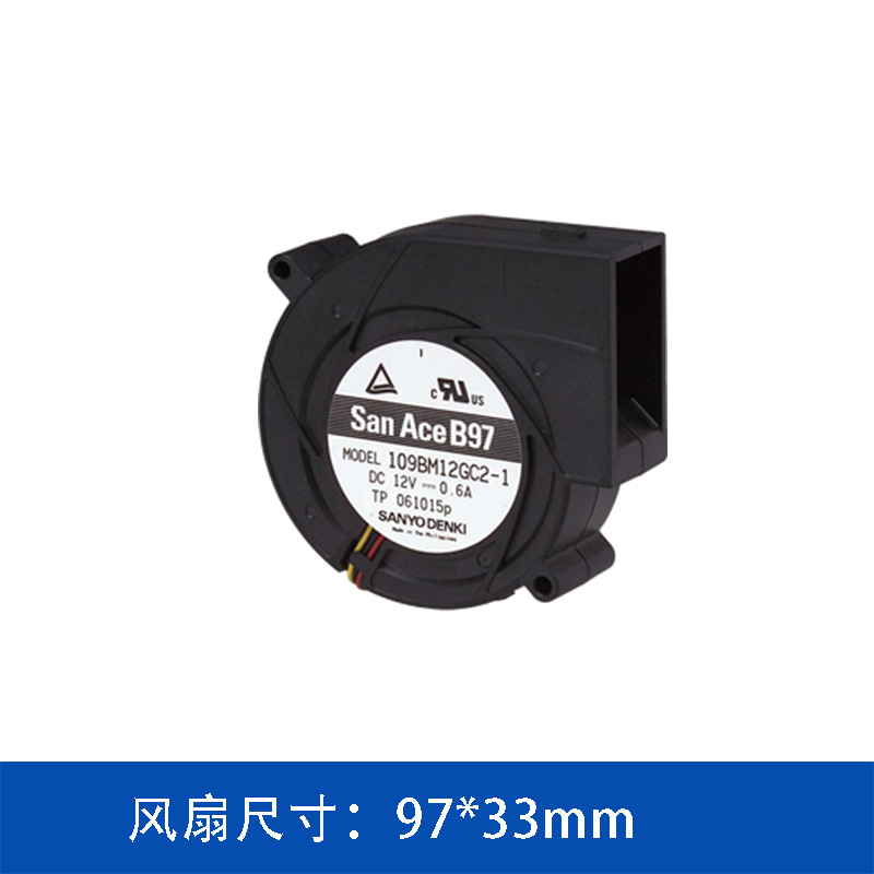
For applications using a 24V DC power system, the 109BM24HC2-1 San Ace blower provides a compact blower configuration with a 97 × 33 mm form factor. Developed under the San Ace brand of SANYO DENKI, this model combines a relatively compact structure with controlled airflow and static-pressure performance for equipment cooling applications.
1. Why Blower Cooling Is Different from Conventional Axial Fans
A conventional axial fan generally moves air along the axis of the impeller. This configuration can be effective when the airflow path is relatively open and the system does not create significant resistance.
A blower, however, is often considered when the equipment requires a more directional airflow path.
Inside an industrial enclosure, the cooling air may need to pass through:
-
Narrow air channels
-
Heat sinks
-
Electronic modules
-
Filters
-
Vented panels
-
Internal partitions
-
Compact duct structures
These components introduce airflow resistance. As a result, simply selecting a fan based on its maximum airflow can lead to an inaccurate assessment of actual cooling performance.
For this type of application, static pressure is an important selection parameter alongside airflow.
The 109BM24HC2-1 provides a maximum static pressure of 204 Pa, with a maximum airflow of 25.1 CFM. This combination gives engineers another option when designing airflow through a relatively constrained internal cooling path.
2. Key Specifications of 109BM24HC2-1
The main specifications of the 109BM24HC2-1 are as follows:
|
Parameter
|
Specification
|
|
Product
|
Blower
|
|
Model
|
109BM24HC2-1
|
|
Brand
|
San Ace / SANYO DENKI
|
|
Rated Voltage
|
24 V DC
|
|
Rated Current
|
0.26 A
|
|
Rated Power
|
6.24 W
|
|
Rated Speed
|
3,300 min-1
|
|
Size
|
97 × 33 mm
|
|
Maximum Airflow
|
0.71 m³/min / 25.1 CFM
|
|
Maximum Static Pressure
|
204 Pa / 0.819 inchH₂O
|
|
Noise
|
48.5 dBA
|
|
Expected Life
|
40,000 h at 60°C / 70,000 h at 40°C
|
|
Sensor
|
Pulse sensor
|
|
PWM Control
|
No
|
|
Ribbed
|
No
|
The specifications show that this model is positioned differently from higher-speed versions in the same blower family. Its rated speed is 3,300 min-1, while the rated power is only 6.24 W.
This makes power consumption another factor worth considering when the cooling system operates continuously.
3. 24V DC Operation for Industrial Equipment
The 24V DC voltage platform is widely encountered in industrial control and automation environments.
Many industrial systems use 24V DC power for control circuits, sensors, actuators and auxiliary equipment. When the cooling fan can operate directly from the available DC supply, the thermal management architecture can potentially be simplified.
For a 24V system, the 109BM24HC2-1 has a rated current of 0.26 A and rated power consumption of 6.24 W.
For equipment designers, this specification is useful during the power-budget stage.
The fan's electrical consumption should be considered together with:
-
Total system power consumption
-
Number of cooling fans
-
Continuous operating time
-
Power supply capacity
-
Fan control strategy
-
Ambient temperature
For example, if multiple fans are installed, the combined fan power should be included when calculating the auxiliary power budget of the complete equipment.
4. 97 × 33 mm Form Factor and Installation Considerations
Mechanical integration is often just as important as airflow performance.
The 109BM24HC2-1 uses a 97 × 33 mm form factor, which provides a relatively compact blower structure for equipment where installation space is restricted.
Before selecting the fan, engineers should evaluate the complete airflow route rather than looking only at the fan dimensions.
Important mechanical factors include:
Air inlet
The inlet should have sufficient open area to avoid unnecessary restriction.
If the inlet is partially blocked by a panel, filter or nearby component, the actual airflow may be lower than the maximum airflow stated in the specification.
Air outlet
The blower outlet should be connected to an appropriate airflow path.
If the outlet immediately encounters a narrow passage or sharp change in direction, additional pressure loss may occur.
Internal ducting
When a blower is connected to a duct, the duct's length, cross-sectional area and number of bends can significantly influence system resistance.
Heat-source location
The cooling airflow should ideally be directed toward the actual heat-generating components rather than simply circulating air inside the enclosure.
This is particularly important for equipment containing concentrated heat sources such as power electronics or processors.
5. Airflow and Static Pressure Should Be Evaluated Together
One of the common mistakes in cooling-fan selection is comparing products solely according to maximum airflow.
For the 109BM24HC2-1:
-
Maximum airflow: 25.1 CFM
-
Maximum static pressure: 204 Pa
However, these two values represent different ends of the fan's performance characteristics. They should not be interpreted as values that will necessarily occur simultaneously under the same operating condition.
In an actual system, the operating point is determined by the interaction between the fan performance curve and the system resistance curve.
This means engineers should consider the following process:
Equipment heat load → required heat dissipation → required airflow → system resistance → fan operating point
This approach is more reliable than simply choosing the model with the largest CFM rating.
6. Noise Can Also Become a System-Level Design Factor
The 109BM24HC2-1 has a specified noise level of 48.5 dBA.
For industrial equipment installed in control rooms, laboratories, medical environments or other noise-sensitive locations, fan noise can become an important design consideration.
Noise is influenced not only by the fan itself, but also by the surrounding structure.
For example, noise can be affected by:
-
Air inlet restrictions
-
Outlet geometry
-
Duct resonance
-
Panel vibration
-
Fan mounting
-
Air turbulence
-
Operating speed
Therefore, if acoustic performance is important, the fan should be evaluated together with the complete equipment rather than tested as an isolated component only.
7. Pulse Sensor for Fan Monitoring
Another feature of the 109BM24HC2-1 is its Pulse sensor.
A pulse output can provide the control system with information related to fan operation. This can be useful for equipment that requires basic cooling-status monitoring.
For example, the system controller can use the fan signal as part of a maintenance or protection strategy.
Potential applications include:
-
Fan failure detection
-
Abnormal operating condition monitoring
-
Preventive maintenance
-
System alarm logic
-
Equipment service diagnostics
For industrial equipment designed for long operating cycles, monitoring the cooling system can be valuable because fan performance directly affects the thermal condition of the electronics.
8. Expected Service Life and Equipment Reliability
According to the supplied specification, the expected life of the 109BM24HC2-1 is:
40,000 hours at 60°C
and
70,000 hours at 40°C.
This difference highlights an important principle in thermal management: operating temperature has a direct influence on cooling-component life.
A fan operating in a high-temperature enclosure experiences a more demanding thermal environment than one installed in a relatively cool system.
Therefore, equipment designers should not evaluate fan life only by looking at a single service-life number. The actual application should also be considered, including:
-
Ambient temperature
-
Internal enclosure temperature
-
Continuous or intermittent operation
-
Dust exposure
-
Installation orientation
-
Airflow restriction
-
Actual fan operating point
A properly designed cooling system can help prevent unnecessary thermal stress on both the fan and the electronic components being cooled.
9. Where Can 109BM24HC2-1 Be Considered?
The combination of 24V DC operation, 97 × 33 mm dimensions, 25.1 CFM maximum airflow and 204 Pa maximum static pressure makes the 109BM24HC2-1 relevant to a range of compact equipment designs.
Potential application areas include:
Industrial control equipment
Control cabinets and automation equipment often contain multiple electronic modules within a limited enclosure volume. A blower can be useful when airflow needs to be guided toward specific areas.
Communication equipment
Communication systems can generate continuous heat during operation. A compact blower configuration can be considered where airflow needs to be directed through an internal cooling channel.
Power electronics
Power supplies, converters and control modules can create localized heat sources. Blower-type cooling can provide a more directed airflow route compared with an unrestricted axial-airflow arrangement.
Electronic equipment
Compact electronic systems may have internal components positioned close together. In these cases, airflow direction and system pressure loss can be important factors during thermal design.
10. How Engineers Should Evaluate This Blower
The 109BM24HC2-1 should not be selected simply because its nominal airflow meets a preliminary requirement.
A more practical engineering evaluation can be divided into five steps:
Step 1 — Determine the equipment heat load
Identify the major heat-generating components and estimate their total thermal load.
Step 2 — Establish the required cooling airflow
Determine the airflow required to maintain the target component or enclosure temperature.
Step 3 — Estimate system resistance
Consider heat sinks, filters, ducts, vents, grilles and internal structures.
Step 4 — Check the fan operating point
Compare the system resistance curve with the blower performance curve.
Step 5 — Verify the actual installation
Prototype testing should confirm temperature, airflow, noise and fan operating conditions under representative loads.
This process helps avoid a common problem: selecting a fan according to a catalogue airflow value without considering the resistance of the actual equipment.
11. 109BM24HC2-1 as Part of a Complete Cooling Design
A cooling fan is only one element of the thermal management system.
The final cooling performance also depends on the equipment's enclosure structure, airflow path, heat-source distribution and heat-transfer components.
For the 109BM24HC2-1, the combination of:
-
24V DC input
-
97 × 33 mm compact form factor
-
25.1 CFM maximum airflow
-
204 Pa maximum static pressure
-
3,300 min-1 rated speed
-
48.5 dBA noise level
-
Pulse sensor
-
40,000 h expected life at 60°C
provides engineers with a defined set of parameters for evaluating its suitability in compact industrial and electronic cooling systems.
The key is to match these specifications with the actual operating point of the equipment rather than treating airflow, pressure, noise and service life as independent catalogue numbers.
12. Conclusion
The 109BM24HC2-1 San Ace blower is a 24V DC cooling solution with a 97 × 33 mm form factor, 25.1 CFM maximum airflow and 204 Pa maximum static pressure.
Its relatively low rated power of 6.24 W, combined with pulse-sensor feedback and a specified service life of up to 70,000 hours at 40°C, makes it a model worth evaluating for compact industrial, communication and electronic equipment where both airflow routing and power consumption need to be considered.
For thermal engineers, the most important selection principle remains the same: choose the blower according to the actual system operating point, not maximum airflow alone. Airflow resistance, heat load, installation structure, operating temperature and monitoring requirements should all be included in the final selection.
Product: San Ace / SANYO DENKI
Model: 109BM24HC2-1
Type: DC Blower
Rated voltage: 24 V DC
Size: 97 × 33 mm
Maximum airflow: 25.1 CFM
Maximum static pressure: 204 Pa
Rated power: 6.24 W
Rated speed: 3,300 min-1
Noise: 48.5 dBA
Sensor: Pulse sensor
 ∷
∷




 Click to inquire
