SANYO DENKI San Ace 9BMB12P2F01: 12V 97×33 mm Blower Cooling Fan for Compact Electronic Equipment
As electronic equipment continues to become smaller and more densely integrated, thermal management is becoming increasingly important in equipment design.
Compact electronic systems often have multiple heat-generating components installed within limited internal space. Heat sinks, ventilation grilles, filters, narrow air passages, and densely arranged components can further increase airflow resistance.
For these systems, selecting a cooling fan based only on maximum airflow may not be sufficient. Engineers also need to consider static pressure, system impedance, installation space, power consumption, control method, and expected operating life.
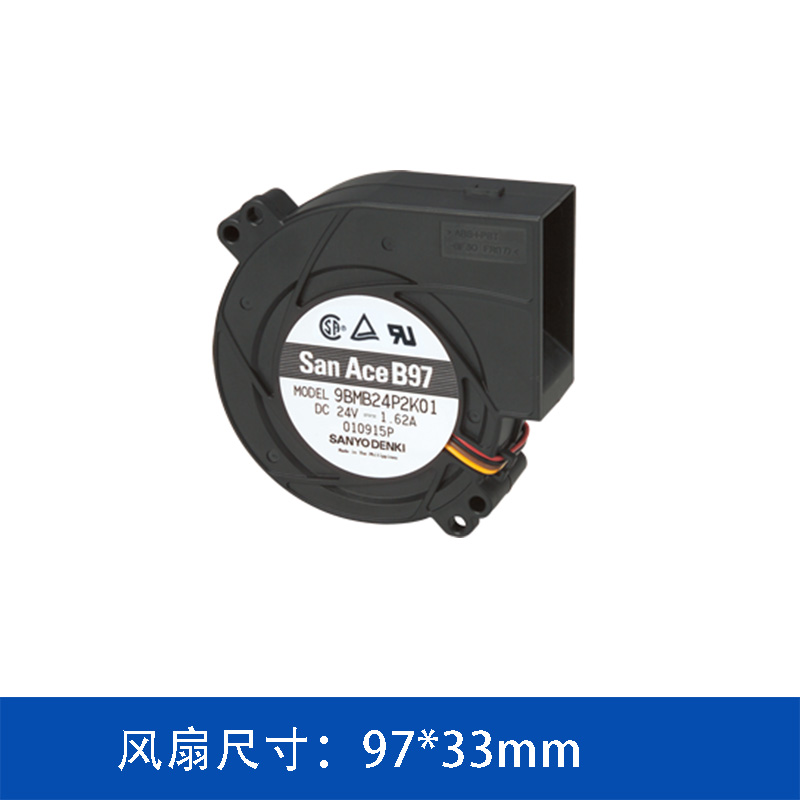
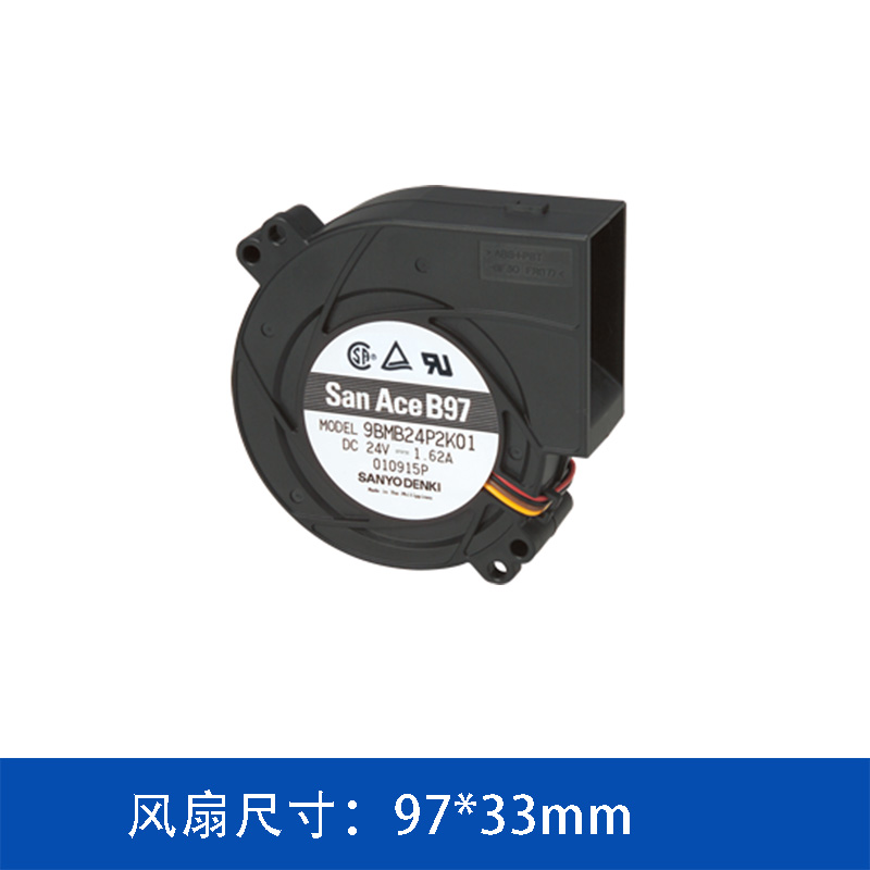
The SANYO DENKI San Ace 9BMB12P2F01 is a 12V DC blower cooling fan with a compact 97×33 mm form factor. It provides 36.7 CFM maximum airflow and 410 Pa maximum static pressure, together with PWM control and pulse-sensor feedback.
Compact 97×33 mm Blower Design
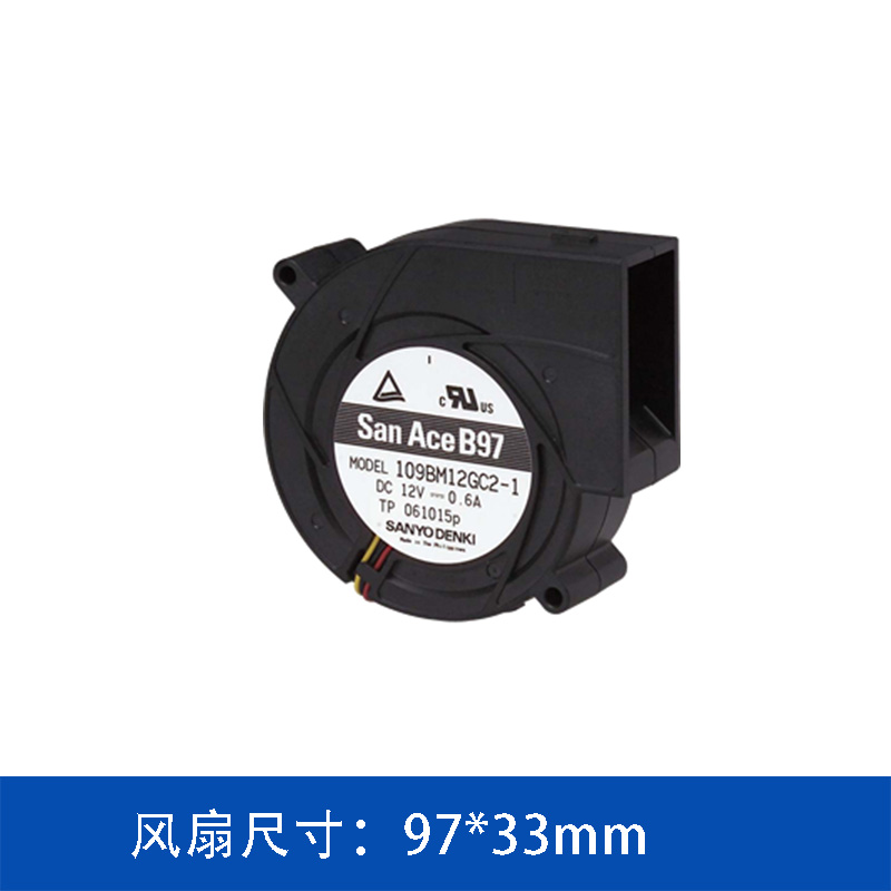
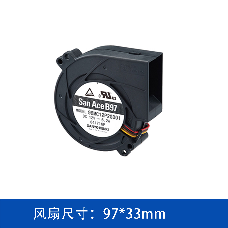
The 9BMB12P2F01 measures 97 mm × 33 mm, making it part of the compact 9733 blower category.
The blower configuration differs from a conventional axial fan in the way airflow is directed.
Air enters through the intake and is discharged in a direction approximately 90 degrees from the intake direction. This allows engineers to redirect airflow within compact equipment without necessarily adding an external duct simply to change the direction of airflow.
This can be particularly useful when the available installation space is limited or when the internal airflow path needs to be carefully arranged around electronic components.
For compact equipment, the physical configuration of the cooling fan can be just as important as its airflow specifications.
410 Pa Maximum Static Pressure
The San Ace 9BMB12P2F01 provides a maximum static pressure of 410 Pa, equivalent to approximately 1.64 inchH₂O.
Static pressure describes the fan's ability to generate pressure against airflow resistance.
In practical equipment, air rarely flows through a completely open path. The cooling system may include:
-
Heat sinks
-
Air filters
-
Protective grilles
-
Narrow ventilation openings
-
Internal ducts
-
Dense electronic components
-
Cable and structural obstructions
All of these elements can contribute to system impedance.
As system resistance increases, the actual airflow delivered by the fan decreases.
Therefore, the maximum airflow specification should not be interpreted as the airflow that will necessarily be achieved after the fan is installed in the equipment.
For engineering selection, the fan performance curve should be evaluated together with the system resistance curve.
36.7 CFM Maximum Airflow
The 9BMB12P2F01 provides a maximum airflow of:
This airflow capacity can support forced-air cooling in compact electronic systems with moderate heat generation.
The actual airflow, however, depends on the operating point of the fan.
A practical cooling design should therefore follow a system-level process:
Heat generation → required cooling capacity → required airflow → system impedance → fan operating point
This is particularly important when the fan is installed inside a compact enclosure where the available airflow path is restricted.
A fan with an appropriate balance between airflow and static pressure can provide more useful cooling performance than a fan selected solely according to its free-air airflow rating.
12V DC Operation and 10.8 W Rated Power
The San Ace 9BMB12P2F01 is designed for 12V DC operation.
Its main specifications are:
|
Parameter
|
Specification
|
|
Model
|
9BMB12P2F01
|
|
Product Type
|
Blower
|
|
Size
|
97 × 33 mm
|
|
Rated Voltage
|
12 V DC
|
|
Rated Current
|
0.9 A
|
|
Rated Power
|
10.8 W
|
|
Rated Speed
|
4,500 min⁻¹
|
|
Maximum Airflow
|
1.04 m³/min / 36.7 CFM
|
|
Maximum Static Pressure
|
410 Pa / 1.64 inchH₂O
|
|
Noise Level
|
56 dBA
|
|
Sensor
|
Pulse sensor
|
|
PWM Control
|
Yes
|
|
Expected Life
|
40,000 h at 60°C / 70,000 h at 40°C
|
With a rated power of 10.8 W, the 9BMB12P2F01 is positioned toward the lower-power side of the 97×33 mm San Ace blower lineup.
This makes it a candidate for applications where forced-air cooling is required but the thermal load does not necessarily justify the higher power consumption of higher-output models.
PWM Control for Adjustable Cooling
The 9BMB12P2F01 supports PWM control, providing the equipment controller with a way to adjust fan operation according to thermal demand.
The heat generated by electronic equipment is not always constant.
A device may operate at a relatively low load during standby or light processing and generate considerably more heat during high-load operation.
With PWM control, the cooling system can be designed to respond to these changes.
A typical control concept may be:
Lower thermal load → lower fan speed
Higher thermal load → higher fan speed
This provides greater flexibility when balancing thermal performance, fan power consumption, and acoustic requirements.
For equipment designers, PWM control can also provide an opportunity to integrate fan operation into the overall thermal management strategy.
Pulse Sensor for Fan Status Monitoring
The 9BMB12P2F01 includes a pulse sensor.
The pulse signal can be used by the equipment controller to monitor fan rotational status.
Fan monitoring can be particularly useful in equipment where cooling performance is directly related to system reliability.
For example, if the fan stops operating or its rotational speed changes unexpectedly, the controller can use the feedback signal as part of a fault detection or thermal protection strategy.
This allows the cooling fan to become part of the equipment's monitoring system rather than functioning only as a standalone airflow component.
Expected Service Life at 40°C and 60°C
The expected service life of the 9BMB12P2F01 is specified as:
40,000 hours at 60°C
70,000 hours at 40°C
Operating temperature is an important consideration when evaluating fan service life.
The temperature around the cooling fan may be considerably higher than the surrounding ambient temperature because of heat generated by electronic components.
Processors, power supplies, storage devices, communication modules, and power conversion components can all contribute to higher internal temperatures.
Therefore, fan selection should consider the actual operating environment of the fan.
The final design should take into account:
-
Ambient temperature
-
Internal enclosure temperature
-
Component heat generation
-
Fan installation position
-
Airflow direction
-
Operating speed
-
Continuous operating conditions
These factors can influence the thermal environment experienced by the cooling fan.
Applications of the 9BMB12P2F01
The compact size, blower configuration, PWM control, and moderate static pressure capability allow the 9BMB12P2F01 to be evaluated for a variety of electronic cooling applications.
Server and Storage Equipment
Servers and storage systems often contain multiple heat-generating components within limited enclosure space.
The internal airflow path may include heat sinks, protective structures, and other components that increase airflow resistance.
With 36.7 CFM maximum airflow and 410 Pa maximum static pressure, the 9BMB12P2F01 can be evaluated for compact systems requiring forced-air cooling.
Communication Equipment
Communication and networking equipment can operate continuously and often requires stable thermal management.
The 97×33 mm blower form factor provides flexibility for equipment designers working with restricted internal space.
PWM control can also allow fan operation to be adjusted according to system load and temperature.
Industrial Electronics
Industrial controllers, automation equipment, test instruments, and other industrial electronic systems may require forced-air cooling within compact enclosures.
The blower's 90-degree airflow configuration can provide additional flexibility when arranging airflow around internal components.
The model may therefore be considered where space constraints and airflow routing are important parts of the mechanical design.
Compact Electronic Devices
The 9733 blower form factor is suitable for situations where installation space is limited but forced-air cooling is required.
The combination of:
10.8 W rated power
36.7 CFM maximum airflow
410 Pa maximum static pressure
provides a balanced configuration for equipment with moderate thermal requirements.
Why Airflow and Static Pressure Should Be Evaluated Together
When selecting a cooling fan, maximum airflow is often the first specification engineers compare.
However, maximum airflow is normally measured under free-air conditions.
Once a fan is installed inside an actual device, the airflow path creates resistance.
For example, a cooling system may contain a heat sink, filter, grille, or narrow air channel. Each component increases system impedance.
If the fan does not provide sufficient pressure capability, the actual airflow can fall significantly.
Therefore, fan selection should consider both:
Airflow
and
Static pressure
For the 9BMB12P2F01, the key specifications are:
Maximum airflow: 36.7 CFM
Maximum static pressure: 410 Pa
The actual operating point should be determined from the fan performance curve and the resistance characteristics of the complete equipment.
This approach allows engineers to select a cooling fan based on actual operating conditions rather than relying only on laboratory free-air specifications.
9BMB12P2F01 Key Specifications
The main characteristics of the SANYO DENKI San Ace 9BMB12P2F01 can be summarized as follows:
-
97×33 mm compact blower
-
12V DC operation
-
10.8 W rated power
-
4,500 min⁻¹ rated speed
-
36.7 CFM maximum airflow
-
410 Pa maximum static pressure
-
56 dBA noise level
-
PWM control
-
Pulse sensor
-
40,000-hour expected life at 60°C
-
70,000-hour expected life at 40°C
These specifications make the model a candidate for compact electronic equipment where controlled forced-air cooling, airflow direction flexibility, and moderate static pressure performance are required.
Conclusion
The SANYO DENKI San Ace 9BMB12P2F01 is a 12V DC 97×33 mm blower cooling fan designed for compact electronic equipment.
With a maximum airflow of 36.7 CFM and maximum static pressure of 410 Pa, it provides a balanced cooling solution for systems where airflow resistance must be considered.
Its 10.8 W rated power makes it a lower-power option within the 9733 blower lineup, while PWM control provides flexibility for variable-speed cooling according to equipment thermal demand.
The integrated pulse sensor can also be used for fan operation monitoring and system protection.
For servers, storage systems, communication equipment, industrial electronics, and other compact devices, the San Ace 9BMB12P2F01 can be evaluated when compact installation, forced-air cooling, airflow resistance, controllable fan operation, and long service life are important considerations.
For final selection, engineers should evaluate the complete thermal system, including heat generation, required airflow, system impedance, fan operating point, operating temperature, installation space, control method, noise requirements, and expected service life.
 ∷
∷



 Click to inquire
